| Prev | ICM User's Guide 16.11 Fragment Linking Core Replacement | Next |
| Available in the following product(s): ICM-Pro | ICM-VLS | ICM-Chemist-Pro |
This feature finds the best scaffold replacement or linker fragment from a database. It lets you interactively select two or more points of connection or replacement and search for possible fragments in the 3D database (SDF or Molsoft local database MOLT). The cutting bonds used to define scaffold are matched against a 3D database with a certain RMSD cutoff (usually very small). The best superposition is taken for the original compound and the chemical is minimized. The result is returned as a standard Ligand Editor hit list where results can be easily browsed, sorted and compared. Linker prediction can be made in the presence or absence of the receptor. Filters such as energy strain, maximum number of rotatable bonds and contact distance to the receptor can be used.
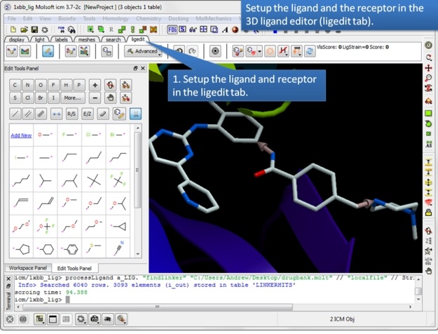 |
| Step 1: Setup the ligand and/or the receptor in the 3D ligand editor. If you have fragments already made you should select the fragments and then choose "Selection" in the drop down menu in the ligand setup step. If you do not wish for the receptor to be considered when sampling linkers then just setup the ligand only. Once the ligand and/or receptor are setup it is generally a good idea to minimize the ligand to remove any clashes and optimize the geometry. |
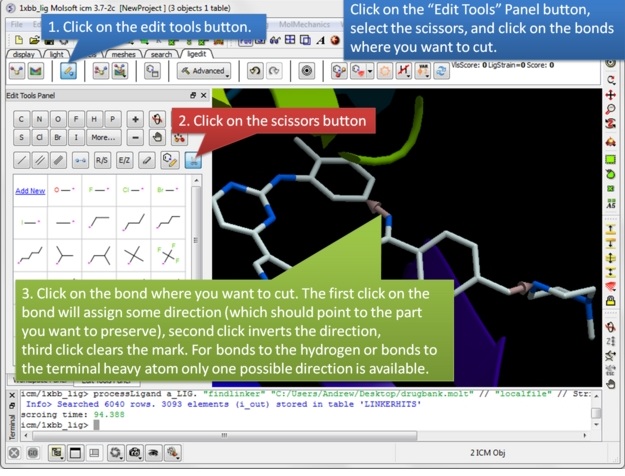 |
| Step 2: Once the ligand and/or the receptor has been setup click on the edit tools button. A panel of editing tools will be displayed, click on the scissors button. Mark two or more bonds using the scissors tool. The first click on the bond will assign some direction (which should point the part you want to preserve), second click inverts the direction, third click clears the mark. For bonds to the hydrogen or bonds to the terminal heavy atom only one possible direction is available. |
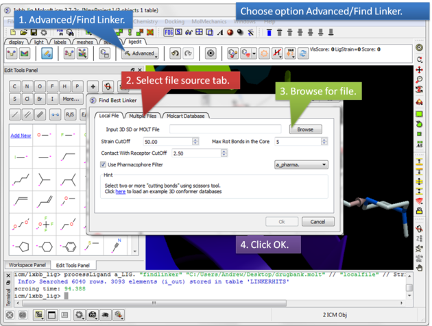 |
| Step 3: Select the Advanced button and choose the option Find Linker. A dialog window will be displayed as shown above which has three tabs.
Screening using the Conformation Database Tab You can choose to screen one ore more SDF files containing 3D coordinates or a molt file that is stored locally on your machine or on MolCart.
|
Screening using the Linker Database Scan Tab
A database of linkers is provided with the ICM distribution - you can screen them using this tab. There are also filtering options available in the panel on the right hand side.
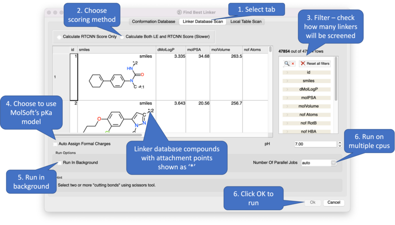
Screening using the Local Table Scan Tab This option allows you to screen your own table of linkers. The linkers must have two attachment points defined by an asterisk.
Results
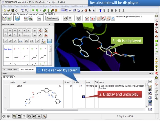 |
| Step 4: Once the fragment fitting has completed a table of results will be displayed. The table is ranked by strain with the top hit in row 1. You can browse the hits using the toggle buttons in the "L" column.
|
Three Point Core Replacement Three cores can be linked by selecting them with the scissors button as shown in Step 1 above. Number of hits will be significantly lower then in 2 point replacement because the extra anchor adds some restraint. We recommend to use larger database for the search (e.g. chembridge100K.molt ) and make sure that ligand is minimized before searching.
|
| Prev Covalent Docking | Home Up | Next Restraints |