[ Superimpose faq | Align 3D faq | Ramachandran faq | Hbonds faq | Interface residues | Res selections | Interface torsions | Packing density | Principal component analysis | Dihedral angle calculation | All torsions table | Hydrophobicity profile | Cavity analysis ]
Optimal superposition implies optimization of the Ca-RMSD upon
rigid body superposition of the equivalent residues/atoms.
This set of equivalent positions can be predefined, or determined
by sequence alignment, or automatically derived from structure.
In the latter case the optimized value is
the RMSD of a trial alignment is corrected by the alignment length
to reward longer alignment with slightly worse RMSD.
The resulting transformation vector is returned in R_out (see the transform
command) .
There are several different algorithms which can be applied: |
|
- superimpose by known residue or atom equivalences (see the
superimposecommand) - superimpose by sequence alignment which is calculated on the fly:
This procedure fails if two structures have no significant sequence similaritysuperimpose a_1.1 a_2.1 align # the sequences are generated on the fly superimpose a_1.1 a_2.1 align minimize # even better method - align .. command to find global structural alignment (returned by the
ali_outvariable) and superimpose accordingly. Here we do not rely on sequence alignement (although it can be added to the optimized scoring function with a certain weight).
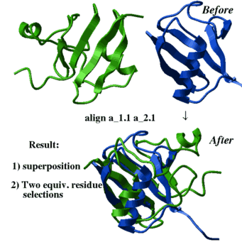
align a_1.1 a_2.1 - Align(.. distance) for local structural alignment
Use
superimpose
command. It performs an optimal rotation and translation of
one structure onto the other. If necessary, a sequence alignment may be
done prior to superposition by specifying align option in the
command line.
Example:
read pdb "3znf"
 display a_1.1//n,ca,c magenta
 make sequence a_1.1
 read pdb "1ard"
 display a_2.1//n,ca,c blue
 make sequence a_2.1
 show sequence
                 # somewhat different sequences of two Zn-fingers
                 # sequence alignment is required
superimpose a_1. a_2. alignsuperimpose a_1.1/16:27/n,ca,c a_2.1/116:127/n,ca,c align
transform g_2_skinGrob R_out # rearrange a related grob accordinglytransform, transformation vector, Rmsd( ) and Srmsd( ).
align ms_molecule1 ms_molecule2
command. There are two variants: a fast superposition using dynamic programming algorithm align [distance] ms_1 ms_2 or a more rigorous, but somewhat less stable and slow align heavy ms_1 ms_2 ... command. This first command is well described above and identifies only the best superposition. The initial superposition is then refined similarly to the find alignment command.
The second algorithm (option
heavy ) identifies a number
of possible superpositions (solutions)
based on the Ca atom coordinates only.
The first solution is the best hit. See also
load solution
command.
Examples:
read pdb "4fxc"
 read pdb "1ubq"
 display a_*.//ca,c,n
 color molecule a_*.
 align a_1.1 a_2.1
 center
 color red  as_out
 color blue as2_out
show ali_out plotRamaEps rs_selection l_addLabel l_addBoundaries Important: if a PDB structure is analyzed,
convert it first to get a proper ICM-object
(true ICM-molecular object does not require prior preparation for building Ramachandran plot).
Example:
read pdb "1crn"
 convert a_1.               # Note, one more object appeared in addition
                            # to the original (PDB) object 1crn
 l_addLabel = yes           # add residue labels to the plot
 l_shadedBoundaries = yes   # add allowed regions to the plot

 plotRamaEps a_2. l_addLabel l_shadedBoundaries
quitconvert it first.
The command show hbond prints list of hydrogen bonds in the text window.
After that they can be displayed.
(Hydrogen bonds can also be calculated by minimize and show energy
commands provided that the hydrogen bond energy term is switched on.)
The display hbond command allows one to show the deviation angle of the hydroben bond from linearity (see the
GRAPHICS.hbondStyle preference ).
Examples:
read object "crn"      # already converted
 show energy
 display
 show hbond 2.5 a_/1:15  # list of H-bonds with H-X distance < 2.5 A
                         # appears in the text window
 display hbond 1.9       # H-bonds shorter than 1.9 A are shown
 GRAPHICS.hbondStyle = 3
 display hbond
See also:
Table(hbonddist,distance)GRAPHICS.hbondAngleSharpness(1.7)GRAPHICS.hbondBallPeriod(1.2)GRAPHICS.hbondMinStrength(1. , allowed range (0.,2.) )GRAPHICS.hbondWidth(0.6)GRAPHICS.hbondBallStyleGRAPHICS.hbondRebuildGRAPHICS.hbondStyle(label style)
Sphere and Acc .
Suppose, you analyze 3D structure of a complex of two molecules, and
would like to see what residues are at the interface. It can be done
by the following:
read object "complex"
 display a_1,2//!h*         # display both molecules
                            # without hydrogens

 color a_1 yellow
 color a_2 green

 show area surface a_1//!h* a_1//!h*      # calculate surface of
                                          # the 1st molecule only

 color red Sphere(a_2//* a_1//* 4.) & Acc(a_1/*)# interface residue atoms
                                              # of the 1st molecule
                                              # in 4 A radius vicinity
                                              # of the 2nd molecule

 show area surface a_2//!h* a_2//!h*      # calculate surface of
                                              # the 2nd molecule only

 color blue Sphere(a_1//* a_2/* 4.)&Acc(a_2//*) # interface residue atoms
                                              # of the 2nd molecule
                                              # in 4 A radius vicinity
# of the 1st moleculeRes () command:
....                                         # same as above.
 ....
 resAtInterf =  Res( Sphere(a_2//* a_1//* 4.)) & Acc(a_1/*)
display residue label resAtInterfselection
in these two examples (usage of two slashes for atom selection,
and one slash for residue selection):
Sphere(a_1.1/* 4.) versus Sphere(a_1.2//* 4.) and also
Acc(a_1.1/*) versus Acc(a_1.2//*)
for specifying residues and atoms, respectively.
Important: when calculating surface, be sure that you properly specify the selection arguments in the show area surface command.
Acc ( rs_ [ r_threshold ] ) function. It will return all residues
for which relative residue solvent accessibility is larger than certain limit
( by default it is 25% of its fully accessible surface ).
To use the function you need to get rid of water molecules and use the
show surface are command. Follow this example:
read pdb "1crn"
 delete a_W                # delete water molecules
 show surface area         # compute exposed surface areas for each residue
 show Acc( a_/* , 0.25 )   # show all residues exposed more than 25%)
 show !Acc(a_/* , 0.25 )   # show buried residues
Converting the selection into other formats
You can also show the selection in a different format, e.g.
String( Acc( a_/* ))  # or
 a_1crn.m/1,5:8,11:12,14:15,17:20,22:25,28:29,31,33:34,36:46
	 Label(  Acc(a_/*))
 #>S string_array
 T1
 P5
 S6
 I7
 V8
 S11
 ...
Identifying buried polar residues
About 50% of all residues have relative accessibility less than 25%. Polar residues typically do not like to be buried. The charged residues like it even less, and if they are buried they usually form a salt bridge. Example:
read pdb "1qau" # neuronal nitric oxide synthase
display
display xstick a_/62,121 # buried asp and arg form a bridge
To identify buried charged residues, use combine the previous selection of the buried residues with specific residue type selection, e.g.
read pdb "1qau"
delete a_W
show surface area
show a_/asp,glu,arg,lys & ! Acc( a_/* 0.15 )0.15 as the burial threshold.
Feel free to modify the selection of residue types above to find other buried
residues.
Identifying exposed hydrophobic patches
A similar technique can be used to identify hydrophobic patches:
read pdb "1qau"
  delete a_W
  show surface area
  show a_/leu,ile,val,met,trp & ! Acc( a_/* )  # buried ones
  show Acc( a_/leu,ile,val,met,trp )           # exposed hydrophobs
To find clusters of exposed hydrophobic residues, use the
Sphere function.
The Sphere function returns atoms, and they need to be converted to residues
with the Res function.
exposed_hres =  Acc( a_/leu,ile,val,met,trp )
  for i=1,Nof(exposed_hres )
    nbrs = Res(Sphere( exposed_hres[i] exposed_hres , 5.0 ))
   if Nof( nbrs ) >= 2 show nbrs   # show pairs of exposed hydrophobs
endforread object "complex"
display a_1.1,2//!h* # display both molecules
# of the complex w/o hydrogens
color a_1.1 yellow
color a_1.2 green
show area surface a_1.1//!h* a_1.1//!h* # calculate surface of
# the 1st molecule only
a1=Sphere(a_1.2//* 7.) & Acc(a_1.1//*) # define the 1st molecule atoms
# belonging to the interface
# of the 1st molecule
# in 7 A radius vicinity
v1=V_1.1//S & a1 # identify standard geometry
# torsions of the 1st molecule
# belonging to the interface
color red Atom(v1) # color atoms which torsions
# belong to
# similar for the 2nd molecule
show area surface a_1.2//!h* a_1.2//!h*
a2=Sphere(a_1.1//* 7.) & Acc(a_1.2//*)
v2=V_1.2//S & a2
color blue Atom(v2)skin (molecular surface) and solvent-accessible
surface of water probe centers (which is one water radius away from the skin ).
The following is an example of how it may be done for a fragment of
a protein.
read object s_icmhome+"crn"
  asel = a_/5:15
  show volume skin asel
  rskin = r_out
  vwExpand = 0.
  show volume surface asel
  rsurf = r_out
  print "skin volume = ", rskin, "; vw volume = ", rsurf
print "packing density = ", rskin/rsurfDisgeo function.
The following example shows how to get a two-dimensional
distribution of amino acid sequences of a series of Zn-fingers given
the distance between sequences is defined by
Distance( sequence1 sequence2 ) function.
This distance is essentially a measure of sequence similarity:
the distance is 0. for two identical sequences, it is proportional
to percent identity divided by 100. for very similar sequences
and goes above one at about 30% sequence identity, tending to
infinity for very small seq. identity numbers.
read sequences s_icmhome+"zincFing" # read sequences from file,
 list sequences              # see them, then ...
 group sequence alZnFing     # group them, then ...
 align alZnFing              # align them, then ...
 a = Distance(alZnFing)      # calculate a matrix of pairwise
                             # distances among them
 n=Nof(a)                    # number of points
 b=Disgeo(a)                 # calculate principal components
 corMat = b[1:n,1:n-1]       # coordinate matrix [n,n-1] of n points
 eigenV = b[1:n,n]           # vector with n sorted eigenvalues
 xplot  = corMat[1:n,1]
 yplot  = corMat[1:n,2]
                             # plot 2D distribution
plot xplot yplot CIRCLE displayValue( )
function. You need to
convert
an object into the ICM type if necessary.
Example:
read pdb "1crn"        # read it in
 convert                # quickly convert into ICM-object
 show v_//phi,psi       # just show all phi,psi's
 show v_/3:17/xi*       # show chi angles of residues from 3 to 17
a = Value(v_//phi,psi) # create a real array of values of spec. torsionscalcDihedralAngle macro.
If this macro is loaded, you can do the following:
read object "crn"
 as_1 = a_/1/n,ca,c
 as_2 = a_/3/n,ca,c
 display a_//n,ca,c blue
 color as_1 magenta
 color as_2 green
 calcDihedralAngle as_1 as_2
print "dihedral angle 1(n,ca,c) and 3(n,ca,c) (deg) = ", r_outas_1 = a_/1/ca,c,n
as_2 = a_/3/ca,c,n
calcDihedralAngle as_1 as_2
print "dihedral angle 1(n,ca,c) and 3(n,ca,c) (deg) = ", r_outAcos( ),
Length( ),
Sum( ),
Vector( ).
show V_//*               # or
 show V_//phi*,psi*,omg*  # or
show V_//xi* # side chain torsionsprintTorsions, for example:
read pdb "1crn"
 convert
printTorsions a_/2:15 Kyte and Doolittle, 1982
or use your favorite one. (Note, there should be 26 entries in the
hydrophobicity parameters list hPhobInd corresponding
to the 26 letters of the alphabet. Non-participating letters
B,J,O,U,X,Z are marked by zero values.)
# define a hydrophobicity scale
 hPhobInd = { 1.8,  0.0,  2.5, -3.5, -3.5,  2.8, -0.4, \
             -3.2,  4.5,  0.0, -3.9,  3.8,  1.9, -3.5, \
              0.0, -1.6, -3.5, -4.5, -0.8, -0.7,  0.0, \
              4.2, -0.9,  0.0, -1.3,  0.0}

                                  # make a macro
 macro hPhobProfile seq_ i_windowSize
   if (Type(i_windowSize)=="unknown") then
     i_windowSize = Ask("Enter window size",windowSize)
   endif
   R_window = Rarray(i_windowSize,1./i_windowSize)
   R_hphob  = Smooth (Rarray(seq_,hPhobInd),  R_window)
   R_ruler  = {0.,0.,10.,10.,0.,0.,0.,0.}
   R_ruler[2] = Real(Length(seq_))
   r_tic = 1./Sqrt(Real(i_windowSize))
   r_tic = Integer(r_tic*100.0)/100.
   R_ruler[5] = -7.*r_tic
   R_ruler[6] =  7.*r_tic
   R_ruler[7] = r_tic
   R_ruler[8] = r_tic
   print R_ruler
   s_legend = {"Hydrophobicity plot","Sequence","Hydrophobicity"}
   xplot = Count(1 Length(seq_))
   yplot = R_hphob
   psfilename = "hphob"
   plot xplot yplot R_ruler s_legend grid="xy" display psfilename
   delete R_window R_ruler r_tic
 endmacro
                                  # now, an example
 read object "crn"
 s = Sequence(a_)
hPhobProfile s 7Examples:
read object "crn"  # or whatever
 make grob skin "g_skin"
 split g_skin
 nShells = i_out
 display wire residue labels
 for i=1,nShells
   v = Volume(g_skin$i)   # actually its surface is returned in r_out
   s = r_out              # there is no need to use the explicit Area(g_skin$i)
   if(v > 0.) then        # note that cavities have negative volume!
     display transparent smooth g_skin$i
     printf "Shell  %d: V=%f A=%f\n", i, v, s
   else
     display reverse smooth yellow g_skin$i
     center g_skin$i
     printf "CAVITY %d: V=%f A=%f R~%f\n", i, -v, s, -3.*v/s
   endif
# add pause here for an interactive session
 endfor